Friday, November 30, 2012

ELECTRONICS: Self taught beginnings.

I admit that the spinners I had built off of the solar engine instructions in the Junkbots... book were built off of instructions, and I really had little Idea of even how the solar engines worked at that point. so, I got a bit serious on discovering things on my own, so that I would know about them without trying to remember lessons learned by rote, or comprehend the paragraphs I just read on things I didnt fully understand yet- that was why I wanted hands-on personal experience.

So, where to begin? Transistors. I knew there were two basic types. NPN and PNP, each with varying performances and attributes, that could be looked up on datasheets online. But I had no need for trivia. I knew most things I build would be low voltage, trickle charged, or running off of a 9volt at most.

So, I set up my little power supply, set it to 3V, and placed an NPN transistor in the center, and put 3 jumper wires inline with the 3 rows the prongs were stuck into. I kind of figured that N stood for Negative, and P for Positive, so I tried putting + to the P part (middle pin), Then an LED to one pin to power, to ground, then the other side, until I got to a point where the darn thing switched the LED on and off with me pulling the middle pin out. I eventually figured out that the two side pins were basically like NO (Normally open) contacts on a relay (which I understood as an electrician), with the middle pin being the "coil". With that figured out I now knew that transistors were tiny little switches.
This is a re creation of my eventual "Eureka!" moment, of getting the transistor(lost between the jumper prongs) to "do its thing"


Doing a little more "exploring and trying everything" I found out that the NPN transistor didnt really matter which way the current flowed through the ends (collector and base), and it was basically a "conductor". What was odd in my "try everything" was that with power to the base, and either side having the LED, the light would still come on... without anything on the other prong. I didnt know what to do with this little tidbit of knowledge (still cant think of any reason to), but the point is that now I DO know it, and its a part of my experience, not just something I read. So its with me now.

Next I looked into the "amplification" factor of transistors; how a weak change in the Base makes a BIG change in the mainline power flowing through the ends. Trying to keep robotics in mind, I used a photoresistor to drive a small motor at different speeds with different light levels. It didnt work very well by itself. The resistance was just too high for the 5V to push through the resistor AND drive the little motor. So I tried the photresistor as a variable current into the base of an NPN, to see if this "amplification" thing would do what I thought. It didnt. The resistor varied the current to the base, but this only resulted in an on, or off state to the motor, which did in fact drive now, just all the time, using the transistor as a pathway for the power.

It was time to do some thinking. I had read up in a "beginning electronics" book about "voltage dividers" and knew a bit about the ohms law theory of it all (electrician, remember); about how the voltage drops were divided up evenly along the different loads in a series circuit.  This gave me a little lightbulb moment: "maybe I dont adjust the current to the base, but rather the VOLTAGE!" I eagerly put the photoresistor from power to base, like it was before, only now added a 1k ohm resistor from that base to ground.. this should vary the voltage to the base as the resistance of the photresistor changes between its 10k ohm and 2k ohm range. It worked GREAT!

After making a system that worked, I then went on to make something to keep my interest going: I made a Robot Eye.
Point of note: it was built to look like an eye- with "neuron" blob solder joints, to tangled optic nerve wires- on PURPOSE. :) It is really as simple as a photoresistor, a NPN transistor, a 1k ohm resistor, and 3 color coded wires: Red= + voltage, Green= Ground, Black= Motor power lead.


Having a purpose to strive for made all the puzzling out less tedious. I now had an Eye that could vary the speed of a wheeled motor. Cross connect the eyes to the opposite motors, and the eye facing the light would make the opposite wheel go faster, making it follow/chase a light around.  THAT is the far off goal that keeps me at it!

Oh, how about a video of the Eye driving a wheel?

So yeah, progress was made rather quickly with simple level electronics aimed at doing something "neat". That wheel/geared motor, by the way, used to be a TrekBot.
http://www.mydeskpets.com/trekbot/
These are found at RadioShack, and are pretty much mass produced BEAM bots all in themselves. I bought a couple of these, played with them the prerequisite amount, then promptly tore them apart for parts, and a rather cool hubless wheel design.

I asked the People at DeskPets if it was ok to "hack" their toys, in order to make other things with them, and that I was intereted in making some of them into BEAM photovores instead of remote control. They replied that it was perfectly fine, they love BEAM hacking too, and even gave me the pinouts of the tiny chip inside that drives the H-bridges to fwd or reverse the wheels!!! That was above and beyond what I expected, those guys are awesome! and make some pretty cool gizmos, as well.

The SkitterBot, TrekBot, and TankBot are my favorite. I have bought (and frankenstein monster'ed) many of them over the months.

Thursday, November 29, 2012


SPINNERS.

This is a good representation of my slow but steady improvement in making basic BEAM bots that dont do too much... just spin.

Lets start off with my old Symet, built from the Book instructions (Junkbots, etc). WOW what a klunker!!:
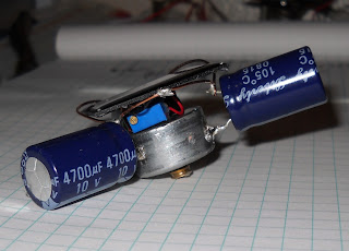
That is a 1/4" grid graphpaper, so you can see just how HUGE-UH this thing was. its actually kinda silly looking nowadays. The thing was, I couldnt find any low voltage 4700 Caps (like the one in the transistor testor) at the time, and used all I could get: 10volt ones. I know now they are simply MUCH too heavy to make a solar powered thing that actually uh.. does anything.

Above it is the qeue cards I started making for myself, little reminders on circuit designs of stuff I may come back to later and need a quick reminder on what goes where.

The motor is a pancake motor I got from a Cassette walkman from the 80s/90s- I did what the Book reccomended, and asked my coworokers if they had any old walkmen tapedecks laying around that they didnt want anymore.. and BOY did they start coming in! I got like 5 of them to tear apart for the rather excellent motors to be had within (this one ran on 1.7 volts, drawing only 35mA- with some pretty good torque, by way of example). The Solar cell is one of several I mail ordered from Solarbotics. These poor cells are having a hard living, but they are resin encased, so, except for the printed circuitry tabs tearing away, theyre pretty much indestructable.  BTW: that little cell, measuring 37x33mm.. is a 6 volt, ~50ma (!!!)
This side view shows how it is supposed to work- the pulley (smeared in dried school glue for better grip) sits at an angle, propped up on the edge of the Capacitors, just barely not dragging the case on the ground. What this does is when the motor turns on, say, clockwise, like this the symet will slide towards me, until it runs into something, tips anoter way, and now the turning wheel will send it skitting in some other direction. Pretty cool, but all my klunky old thing can do is twitch. (and UGH the lousy cold welds on the casing!!!)

But anyway, that is the first I ever built.

Next is one from a failed experiment. I call it "1Wing":
This one has the smaller 4700 cap, and a different solar engine than the first Symet (that was a flashing LED solar engine). This one is a fancier 1381c solar engine, using a special voltage trigger chip- one of those transistor looking things crammed in between the capacitor prongs. That little black blob with the red diode is indeed the entire engine.
This is "1Wing" because it was supposed to be one side of a pair- in an attempt to make a Photovore that didnt actually have any eyes, yet still tracked towards a light due to the solar engine getting the most light firing more often, turning the bot to it (by running the opposite side motor). The blind photovore failed as a prototype, because for some reason one wing worked extra well, the other maybe 1/3 as well... meaning it didnt do what I wanted it to do. bummer.
 
But I kept the good solar engine, put the motor on its own wing, and made it a sort of spinner. This was my forst working solar engine that actually... worked.
 The cell is actually one of the big ones, cut down the center, where the two arrays of cells inside the resin are separated. I realized that the 6V was really just 2 3v ones wired in series, so that actually meant I could make 2 cells out of one!
 
Heres a rather boring video of it doing something... but what makes me grin is that "look Ma, no batteries!", and it really is running off of the desklight.
Yeah.. I warned you it wasnt very exciting, dont worry, the rest are much more active, as I DID get better at making these things.
 
 
So what was next... OH my "little engine that could":
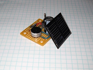
Remember that the grid is 1/4" squares, so thats why its called "little". It uses another cell from Solarbotics, a 22x24mm one, (3v, ~20mA), a tiny pager vibrator motor, and uses the solar engine printed on the back of the card, seen in the next pic.
Kinda messy with the Hot Glue holding it all together. But you may wonder what the point was. This little engine was the end result of me tweaking this and that to take this cell, that Cap, that motor, and make the Best Darn Engine I could out of it, squeaking the most performance out of the limited power trickling in from the daylight. I tweaked mostly just the weight of the chassis, the arrangement of the "wheel" (a glob of tacky hotglue), and the timer capacitor (tan thing) that controls how long the voltage trigger stay "triggered". This is a fine line- between either draining the Cap completely and a slow recharge of the Cap, or a too rapid drain, getting not much motor activity and leaving a full Cap all the time. So you see, even with such few components, something as simple as a timing Cap can make ALL the difference!
 
 
Heres a video showing the best performance I was able to get: the lightest possible setup, the most direct wheel to ground drive, the best "power curve" of pulses:

 Yeah.. pretty Active.. if I do say so myself, running under a 100watt desklight. But why is it the "Little Engine THAT COULD"?
 
Because it could "turn over"!! The charge/discharge cycle, if given enough light, could cycle in between the time it takes for the motor to coast to a stop.. so... it runs continuously!
This is a big deal for me, because its important to know that the cell, with its trickle of current, could NEVER direct drive the motor on its own, directly. But with a Solar engine, and a millisecond short cycletime of pulses, it could in fact do the job!
 
 
Now that just warms my Heart. This little gizmo, about the size of a quarter, would run nonstop everyday until the end of time, or until a breakdown happens (so take THAT Zombie apocalypse! LOL). Maybe I will have it encased in a plexiglass domed display case on my tombstone for all the world to marvel at... too much? ah well, the inner geek in me got carried away.
 
But next lets see what a SERIOUS solar powered spinner can do: This one is bought from Solarbotics, and is called a "Battle Symmet" from an Instructables article(http://www.instructables.com/id/Solar-Powered-Battle-Symet-BEAM-Style/), and comes in a "solder it yourself" kit bag of parts. Lets see... linky:  http://www.solarbotics.com/product/60010/
When I saw this parts list, the somewhat BEAM educated geek in me went OOoooH! over some of the parts: a coreless induction pager motor, a .33F (thats like 330,000uf) SuperCapacitor, some wheels that fit on paperclips, etc... I went a little overboard, and bought like 6 of them.
So, if you clicked the linkys above, you know what its supposed to basically look like. I modified mine a bit, 1 for looks, and one for performance (of a sort):
 

I think mine looks meaner, more sleek, more well, just geektastic I guess. I built 3 of them, to battle it out in a slighly bowl shaped styrofoam plate, and kept track of which one was the "champion" by either being most active, hammering the other battle bot around more, or even BREAKING the other bot with a nasty tangle. The losers got disassembled for parts for other things, and the winner got some finishing touches, and a permanent place in my "cool stuff" tacklebox.
In addition to the blade "weapons" on the ring (these are the striking edges, afterall), what makes this little demon a bit more custom is the little scratch you see to the left of the motor, in the printed circuit strip along the left side. If you look closely, you can see tiny green wires in an X cross connecting the corners. What this means is that the two 3v cell arrays in the panel are wired in paralell now, no longer series. So instead of a 6v,~40mA, its theoretically a 3v, ~80mA... that doesnt work so well in less than optimal light (that was the drawback, but I figure all battle arenas will be lit... right?)
So, looking back at ol' 1Wing in its sedately pulsed spins around and around... how does one with some serious performance BEAM components do in comparison? The supercap (the blue chrome thing.. TINY for so much power) takes a bit of time to build up a charge... but when the voltage trigger sets it loose... well, lets just watch:
Pretty much awesome.
 
Thats it for my spinner Phase of learning (oh! I made a rear view mirror spinner, in my truck! details on that later.), but now we come to a bit of sad part of this Hobby and Learning experience. After eagerly absorbing all I can on BEAM robotics, technology, tricks, and events, and many many internet searches for more, more MORE... I noticed something unfortunate... most BEAM related websites havent been updated since roughly 2002!! Meaning the world has apparently "lost interest" YahooAnswers on this subject informed me that the age of discreet electronic components was giving way to integrated components, leaving little things like the voltage trigger in its transistor package a thing of the past- consumer elctronics simply dont have them inside anymore. Nor are these things called "cassette tape players" that need high efficiency motors around anymore.
 
So, bummer. My mean little blade hammer Battle has no one to battle. The timed dragrace solaroller I was designing has no events to compete in.  So these Gizmo's are ultimately just for my own personal "giggle factor". But so be it! Giggle, I Shall! and keep on building!
 
After this slightly disheartening discovery, my focus drifted a bit... but to other neat things. Like Arduino. More on that later as well, because that has some great robotics aspects as well.


Wednesday, November 28, 2012

So, after the first big buying spree, and my foldout table begame a tried and true hobby center, complete with solderin iron, hot glue gun, 100 watt desk light, etc. I dug right in on learning about diodes, capacitors, transistor, etc, with another book I got: Getting started in Electronics:
http://www.solarbotics.com/product/11350/

I already had a good fundamental knowledge of electricity (I am an Electrician by trade, afterall), but knew little to nothing about electronics. This book helped tons. For instance, I already knew things on DC needed power and a ground, and that diodes point a certain way, but what I didnt know was the "pinout" of transistors, what the different types meant, how a capacitor was used, and how it charges and discharges- and at what times., etc.

Breaking out my radioshack breadboard and jumperwires, and the bag of assorted resistors, capacitors, transistors, etc, I began to tinker.

Simple stuff, like putting a NPN transistor in the center, putting power to its Collector, an LED at its Emmiter, and holding a jumper from the Base in my hand.... and figuring out on my own if it needed power or ground to "work".

After figuring things out a bit, and realizing I had a mixed bag of NPN and PNP transistors, and no real cheat-sheet to look up which numbers were which.. I made my first thing: a transistor tester.

I tested it on the breadboard before "hard wiring it permanently. Its basically just 3 pin sockets to take a transistor in front, and a momentary switch that send either power or a ground to the center pin (base). The switch is spring loaded set to power by default, so touching an NPN to the 3 sockets will get me a tone. I could test the transistor by moving the switch- the tone should cease.

To test a PNP, no tone unless I DO hit the switch.

You may notice bit of fancyness going on at the back end. This gizmo got an upgrade recently, as originally it used a battery back of AAAs to run it, And I got tired of replacing them (not from dead batteries, but rather my cannibalizing the battery pack to test/build something ELSE).

So now its Solar/Desk light powered. The big capacitor (4700uf) is for PNP testing- while an NPN will tone constantly off the Solar cell power, a PNP is more demanding (not sure why), so the CAP stays full waiting for the switch to be toggled, and the test will indicate its a PNP with a momentary beep... good enough for me- to have a gizmo that runs off of.. pretty much nothing!

This little Gizmo is one of the few things from my early learning that survived to this day. Mostly because I still use it; whenever I take apart some electronics, harvest the transistors, and want to know what bin to put them in.


My next thing to do was find/build a power supply, that I could wire to my breadboard, and set the power to what I want. I had just learned about a Voltage Regulator chip, like the 7805- that takes whatever power you apply to it, and only lets out 5v... so knew it was pretty straight foreward to do. After surfing the internet for "Variable power supply" schematics, I was happy to see I already had all the parts I needed to build one. After some careful assembly, I now have another neat little Gizmo, I made myself, that, using a 12v wall-wart power supply, can output between .5 and 10v DC.

Here it is, as tiny as my transistor testor (a common theme I seem to have: tiny, solar, and "what I think looks cool"), putting out 3v, as seen on my homemade voltage/amp probe, in the background. The toggle switch between the guages sets which guage the probes are connected to: the switch points to which guage its on.

The power supply has its regulator and rheostat set back at an angle, originally because I wanted to mount this in a small "project case" I got, with an angled front... but it didnt fit, so here it sits, Heat sink supported, and underside solder points lifted off the table top with this neat white stuff: InstaMorph! As seen here its a hard plastic similar to LEGO plastic, but dip it in a pot of hot water (160 degrees), and it turns clear, and has the consistencey of playdough... moldable plastic!!

The stuff is just too cool: http://www.instamorph.com/

Hmm looking at the above photo, I realize it doesnt show just how "what I think is cool" this little sucker is... so lets take a "beauty shot" with no flash.. for a fuzzy but more revealing angle and insight to why turning this thing on still makes me smile:


oh yea!! If it looks like it escaped from a TR0N universe, then its automatically cool in my book! I mean.. why have a boring indicator LED showing that its on, when it could be a SUPER bright blue LED hidden in the works, so it looks like maybe the thing is giving of Cherenkov radiation or something?  :)

But I know you are really loking at the utter chaos that is my hobby desk in the background.

So with this basic set of tools to get me going, I started trying to build some of the junkbots out of the Junkbots, Bugbots, Bots on wheels book. [now for my next post I need to find that old symet...hmmm]

Tuesday, November 27, 2012

BEAM Robotics. The recently discovered thing that has grabbed ahold of my interest and obsessions of late. Its a simple electronics thing, that also meant it was a good way for me to begin self teaching myself hobby electronics- something I was always interested in learning.

BEAM Robotics is simple. No Computers, controllers, or any of that. And what really appealed to me was that you can make little desktop robots that skitter, race around, roll, flip, etc...  and get this- out of  VCRs and old Cassette Walkmen, Printers, DVD players, etc! Those electronics of old, of which I had several gathering dust, have some really excellent DC motors in them, and even if the device itself is broken, the goodies inside are often just fine! I really like the idea of taking stuff apart (things I do anyway) for materials, putting those parts to use in something completely different, doing so with electronics (that I was interested in as a hobby), and getting little robot critters out of the bargain (Sweet!)

*sigh* It all started with this Book at the local Borders bookstore: "Junkbots, Bugbots, and Bots on wheels"
http://www.solarbotics.com/product/jbb/
...that stopped me dead in my tracks while walking through the bookstore (on my shortcut way to the theater) and compelled me to buy it right then and there. I read through it that night, and was instantly HOOKED.

I started looking through my local Radio Shacks for some of the more exotic components, and found that not much to be found, so, Going online I found this really cool site (which you've already been to if you clicked the above link), that catered to just this sort of geek-ery. Solarbotics.com.

http://www.solarbotics.com/

I'm a little embarrassed at how much money THEY got from me, but when the fedex box arrived, I tore into it like a kid at Christmas. Now I had a bunch of solar cells, motors, IC chips, transistors, etc etc. And promptly got right to work!

This was a few months ago, so these next few posts will be me "catching up" and "showing off" :)